LABORATORY FACILITIES
SMALL TRIAXIAL CELL FOR IN SITU 3D SYNCHROTRON MICRO-COMPUTED TOMOGRAPHY (SMT) IMAGING
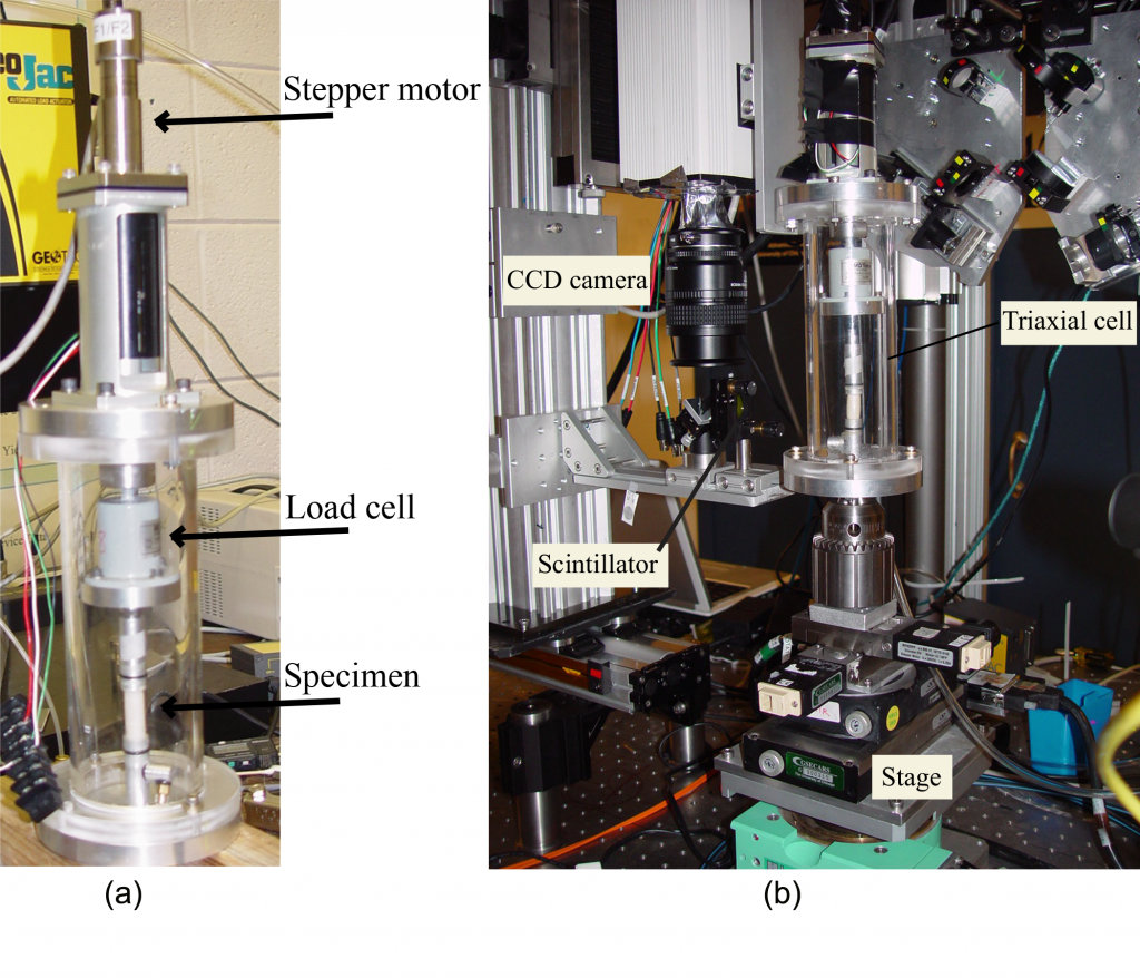
The PI designed and fabricated the small triaxial cell (Figure 1). It can accommodate triaxial specimens with diameters between 10 mm and 30 mm. It weighs only 2800 g, which makes it suitable for mounting on the stage of the SMT scanner. Supporting hardware includes control system for the stepper motor, data acquisition system, power supply to power the load cell and motor, and Labview software to acquire and save measurements for further analysis. A computer-controlled flow pump is used to apply cell pressure and it records the volume change of specimen. Also, specimen volume change can be accurately calculated from the 3D SCT scans.
HIGH-PRESSURE, LOW TEMPERATURE FLOW CELL FOR IN SITU 3D SYNCHROTRON MICRO-COMPUTED TOMOGRAPHY (SMT) IMAGING
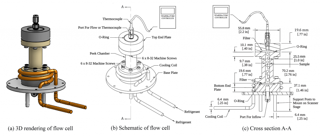
Flow cells with thick-wall steel or aluminum to withstand the high internal pressure are not suitable for SMT scanning since the cell wall will absorb most of the energy of x-ray beam. Therefore, the flow cell must be made from a strong low attenuating material. The PI fabricated a flow cell can withstand an ultimate internal pressure up to 150 MPa with a cooling system to freeze the specimen (Figures 2 & 3). The cell is transparent to x-ray which makes it suitable for in situ SMT scanning. The cell is ideal for investigating gas hydrate formation.
TRIAXIAL SYSTEM:
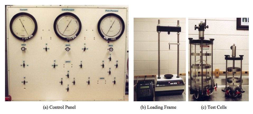
Conventional Triaxial Compression (CTC) experiments can be conducted using the Triaxial System (TS) available at Dr. Alshibli Research Laboratory. It is a fully automated system that capable of performing a wide range of experiments using any stress path for confining stresses that range from 2 to 300 psi. Dr. Alshibli has designed the control panel (Figure 4a), which gives the user the flexibility to swap pressure transducers to cover wide ranges of pore pressure, cell pressure, and volume change. The loading frame (Figure 4b) has a 10,000 lb loading capacity and can be operated manually or fully controlled by a computer interface. Dr. Alshibli also has two triaxial cells to accommodate 4-inch and 6-inch diameter specimens (Figure 4c). All sensors are connected to Fluke Hydra data acquisition unit. Fully automated Experiments are run using Labview software.
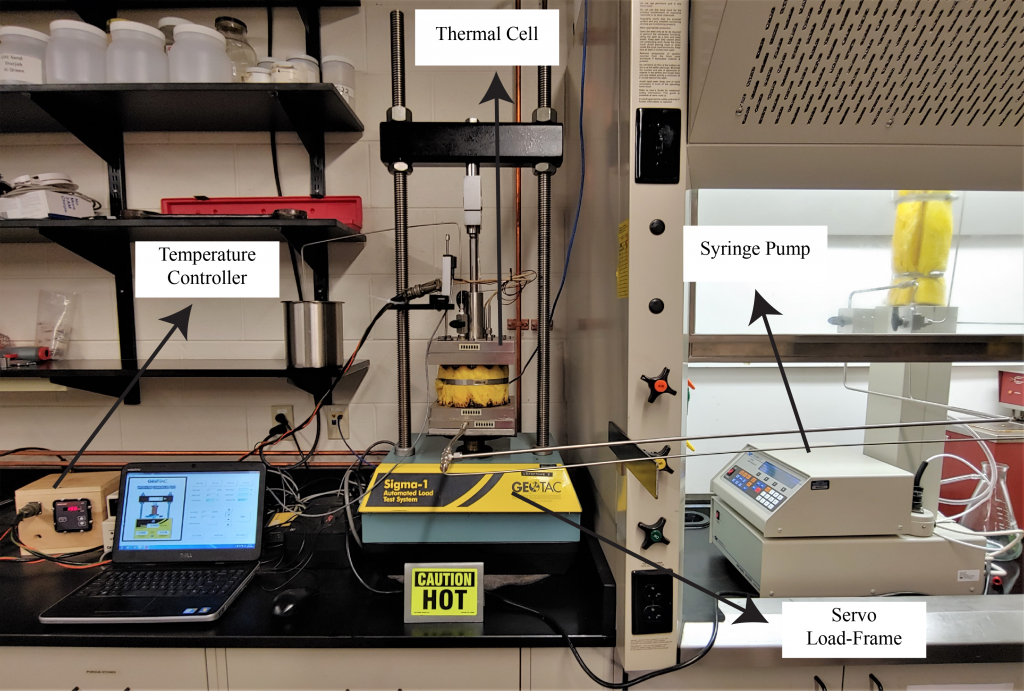
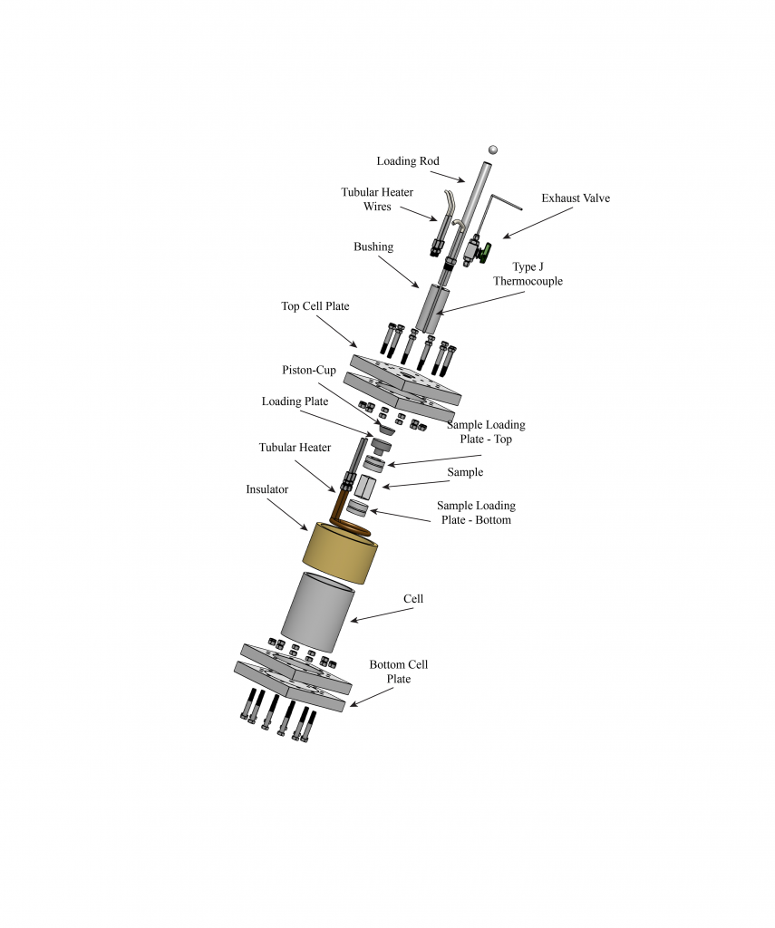
HIGH-PRESSURE THERMAL CELL FOR TRIAXIAL AND CREEP TESTS ON ROCK SALT:
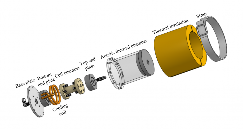
The combination of high pressures and elevated temperatures at the time of experiments makes designing a thermal cell challenging. Our thermal cell can withstand a maximum confining pressure of 15 MPa and a maximum cell temperature of 150 degree C (Figure 5). Figure 6 is an exploded view of all the components of the new high-pressure thermal cell. 316 stainless steel was selected as the design material for the cell to prevent thermal strength losses and corrosion that could potentially happen by testing rock salt. The cell confining chamber has an outer diameter of 127 mm (5 in), a wall thickness of 6.35 mm (0.25 in) and a height of 152.4 mm (6 in) to accommodate the heater and other thermal elements within the cell. The 190.5 mm (7.5 in) long and 25.4 mm (1 in) thick square flanges were welded to the cell chamber. The top and bottom plates are squares with the same length; however, their thicknesses are 25.4 mm (1 in) and 19.05 mm (0.75 in), respectively. A set of 12 3/8 in (9.5mm) fine thread grade 8 bolts and nuts attaches each of the plates to its respective flange. The 19.05 mm (0.75 in) diameter loading rod can transfer axial loads up to 44.5 kN (10000 pounds) to the material being tested. The cell can accommodate specimens with heights up to 70 mm (2.75 in) and diameters up to 44 mm (1.75 in).
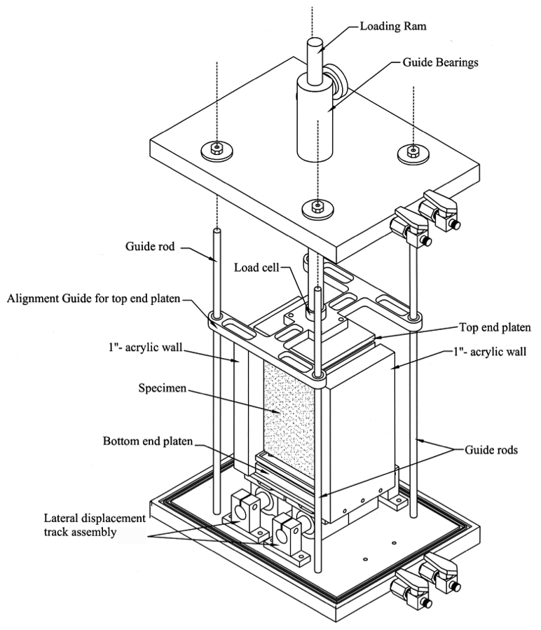
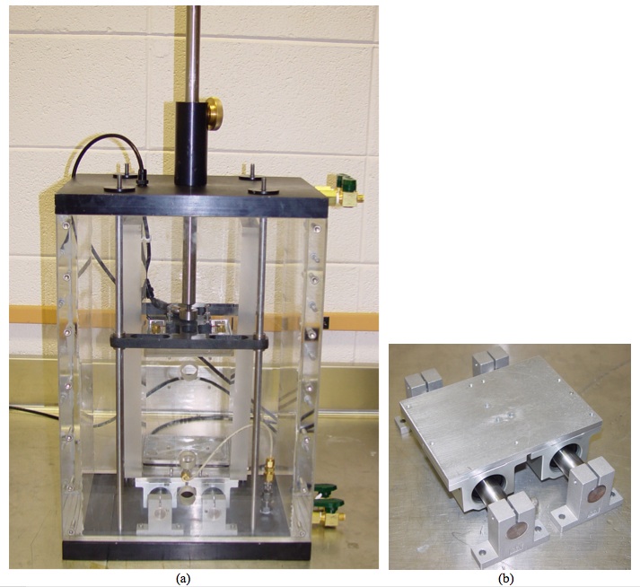
PLANE STRAIN APPARATUS:
Dr. Alshibli has designed and fabricated a Plane Strain Test Cell (PSTC, Figures 7 & 8). It accommodates a prismatic specimen that measures 60 mm wide by 120 mm long by 180 mm high. The plane strain condition is applied via 1-inch thick Acrylic walls to enable easy monitoring of the specimen deformation. The PSTC offers several improvements compared to the device produced by Drescher et al. (1990). It is contained in a prismatic pressure chamber and water is used to apply the confining pressure. The bottom end platen offers the choice of allowing or preventing lateral movement during compression via very low friction bearings (Figure 8b). The top end platen is guided by four internal bearings that prevent platen tilting. The PSTC is also fully instrumented with an internal load cell to eliminate friction with the loading rod and a set of Linear Variable Differential Transducers (LVDT) to record axial and lateral displacements. The triaxial system loading frame and control panel will be used along with the PSTC to perform the PS experiments.
SOME OF RELATED PUBLICATIONS:
- Alramahi, B. A., Alshibli, K. A., Fratta, D., and Trautwein, S. (2008) “A Suction-Control Apparatus for the Measurement of P and S-wave Velocity in Soils”, ASTM. Geotechnical Testing Journal, Vol. 31, No. 1, pp. 12-23.
- Alshibli, K. A. and Williams, H. S. (2005) “A True Triaxial Apparatus for Soil Testing with Mixed Boundary Conditions”, ASTM Geotechnical Testing Journal, Vol. 28, No. 6, pp. 534-543.
- Alshibli, K. A., Godbold, D. L., and Hoffman, K. (2004) “The Louisiana Plane Strain Apparatus for Soil Testing”, ASTM, Geotechnical Testing Journal, Vol. 27, No. 4, pp. 337-346.
Copyright © 2024 Professor Khalid Alshibli