For retaining walls construction, TDOT often allows contractors to excavate behind a retaining wall and replace the existing insitu soils with “select backfill” that has a higher friction angle and permeability which reduces the active earth pressure on the wall. TDOT currently requires that the active zone be excavated at 45o (1:1 slope) from two feet behind the heel of the wall or reinforced soil zone up to the finished grade. Although a 1:1 slope is considered an acceptable temporary slope for average soils in TN, it can be a very conservative approach, and costly, especially when a rock formation crosses the 1:1 slope. Per TDOT retaining wall sheets, a maximum friction angle of 34o can be assumed for the select backfill aggregates that are not tested but meet the requirements stated in Special Provision 624 regarding retaining walls. For select backfill aggregates that are tested independently, TDOT sets the maximum friction angle to a value of 40o or as demonstrated by the test results (whichever is greater). Both values are conservative, as often the submitted independent test results exceed both stated f values. Rankine earth pressure theory is very conservative, to begin with, and the use of a conservative friction angle of backfill material results in a very costly, conservative design of retaining structures with a large backfill zone, right of way, and longer construction time. In addition, there is a need to study the methods of placement of backfill and develop a method of best practice for densifying aggregates. Thus, there is an urgent need to better define the range of expected friction angle values for Tennessee aggregate sources. Using the proper properties of aggregate will result in substantial saving in construction time and money on future projects across the state without compromising safety.
The objective of this project is to collect representative aggregate samples from supply sources throughout Tennessee. Measure properties of aggregates and their shear strength.
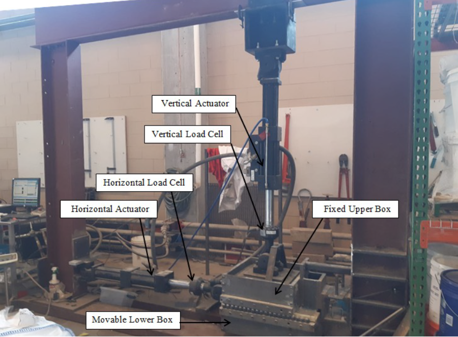
Direct Shear Experiments
A large direct shear box that measures 0.50 m (19.7 in) x 0.50 m (19.7 in) x 0.35 m (13.8 in), and a gap set up at 20 mm was used to conduct the direct shear experiments according to ASTM-D3080. The normal and shear loads are applied using hydraulic actuators and normal and shear displacements are measured using encoders build in the actuators. Each aggregate type was tested at loose (Dr = 30%) and dense (Dr = 80%) states using normal stresses of 35, 70, 105, and 140 kPa (~ 5, 10, 15, and 20 psi) to represent typical stress ranges for fill aggregates behind retaining walls. The normal stress is kept constant while shearing the bottom half of the shear box relative to the stationary top half at a strain rate of 1 mm.