Skip to content Skip to main navigation Report an accessibility issue

Advanced Laboratory Testing of Soils

Figure 1. Isometric view of the PS test cell (the water jacket is not shown)
Figure 2. photograph (without specimen) of the plane strain test cell
Figure 3. A prepared specimen before placing it in the PS test cell
Figure 4. test cell in the loading frame
Figure 5. Specimen preparation mold
Figure 6. Results of a typical experiment
Figure 7. Photograph of a specimen at the end of the test with a marked shear band

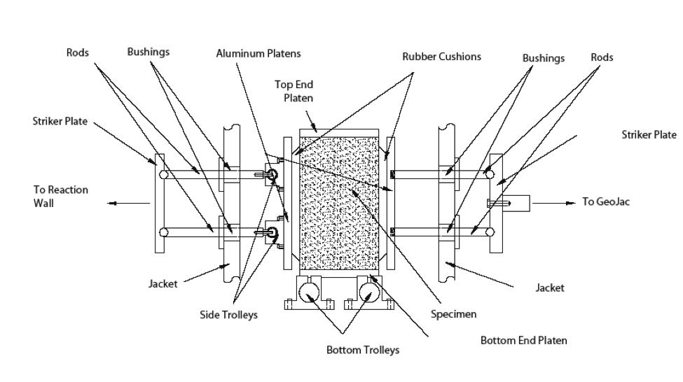
True Triaxial Apparatus with Mixed Boundary Conditions:

Figure 1. 3D schematic of the true triaxial apparatus (water jacket is not shown)
Figure 2. Photo of the test cell of the True Triaxial apparatus
Figure 3a. The horizontal load frame
Figure 3b. The horizontal load frame assembly – schematic of loading in the horizontal direction (some parts are omitted).
Figure 4. (a) Mold assembly partially put together, (b) Mold assembly completely put together with vacuum applied
Figure 5. (a) Specimen placed on vertical trolley; (b) Specimen with mold removed
Figure 6. Test cell in preparation for loading

Related References:

  • Alshibli, K. A. and Williams, H. S. (2005) “A True Triaxial Apparatus for Soil Testing with Mixed Boundary Conditions”, ASTM Geotechnical Testing Journal, Vol. 28, No. 6, pp. 534-543, DOI: http://dx.doi.org/10.1520/GTJ12679
  • Alshibli, K. A., Godbold, D. L., and Hoffman, K. (2004) “The Louisiana Plane Strain Apparatus for Soil Testing”, ASTM, Geotechnical Testing Journal, Vol. 27, No. 4, pp. 337-346, DOI: http://dx.doi.org/10.1520/GTJ19103